Preliminary information on the Micro-Nixie board. © 2013 Cold War Creations.
New micro Nixie board controller. This board supports 4 or 6 digits using 3x2 multiplexing.
* High voltage 180v power generated on board. Requires 9-12vdc @ 350 mA max.
* Supports up to 3.5mA per tube
* Supports 2 sets of colons, either Neon bulbs or LEDs
* 2 Analog inputs, 6 digital input/outputs
* Optional serial connection for
GPS * Fully assembled SMD board.
1. Board size
Board dimensions: 57mm x 30mm x 12mm (2.25" x 1.25" x .465"). Four (4) screw holes, one in each corner for 2-56 or M2 size screws.
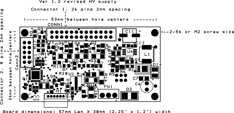

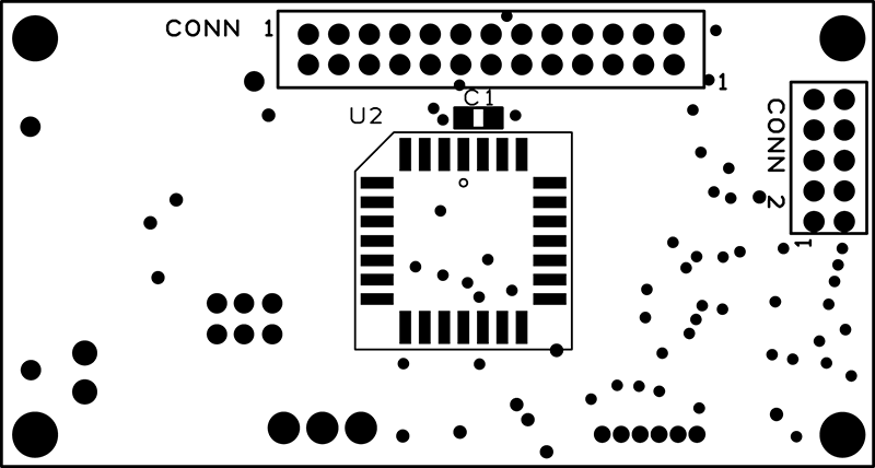

2. Connectors
The board has 4 connectors for Nixie clock interface. The connectors are:
CONN1 - Nixie/Colon interface
A 26 pin 2mm spacing 2 row
connector, pin out below
| Pin 1 | Nixie character '0' | Nixie tubes 0 - 2 |
| Pin 2 | Nixie character '1' | Nixie tubes 0 - 2 |
| Pin 3 | Nixie character '2' | Nixie tubes 0 - 2 |
| Pin 4 | Nixie character '3' | Nixie tubes 0 - 2 |
| Pin 5 | Nixie character '4' | Nixie tubes 0 - 2 |
| Pin 6 | Nixie character '5' | Nixie tubes 0 - 2 |
| Pin 7 | Nixie character '6' | Nixie tubes 0 - 2 |
| Pin 8 | Nixie character '7' | Nixie tubes 0 - 2 |
| Pin 9 | Nixie character '8' | Nixie tubes 0 - 2 |
| Pin 10 | Nixie character '9' | Nixie tubes 0 - 2 |
| Pin 11 | Anode Set 2 | Drives tubes 2 & 5 |
| Pin 12 | Colon 2, neon or LED | Between hours / minutes |
| Pin 13 | Anode Set 1 | Drives tubes 1 & 4 |
| Pin 14 | +12 Volts | For LED colons |
| Pin 15 | Anode Set 0 | Drives tubes 0 & 3 |
| Pin 16 | Colon 1, neon or LED | Between minutes / sec |
| Pin 17 | Nixie character '0' | Nixie tubes 3 - 5 |
| Pin 18 | Nixie character '1' | Nixie tubes 3 - 5 |
| Pin 19 | Nixie character '2' | Nixie tubes 3 - 5 |
| Pin 20 | Nixie character '3' | Nixie tubes 3 - 5 |
| Pin 21 | Nixie character '4' | Nixie tubes 3 - 5 |
| Pin 22 | Nixie character '5' | Nixie tubes 3 - 5 |
| Pin 23 | Nixie character '6' | Nixie tubes 3 - 5 |
| Pin 24 | Nixie character '7' | Nixie tubes 3 - 5 |
| Pin 25 | Nixie character '8' | Nixie tubes 3 - 5 |
| Pin 26 | Nixie character '9' | Nixie tubes 3 - 5 |
CONN2 - Clock I/O
A 10 pin 2mm spacing 2 row
connector, pin out below
| Pin 1 | Function Switch | Port C4 |
| Pin 2 | Mode Switch | Port C5 |
| Pin 3 | Txd GPS/LED control | Port D1 |
| Pin 4 | I/O, Alarm Enable | Port D4 |
| Pin 5 | Rxd GPS (input from GPS) | Port D0 |
| Pin 6 | Alarm Output | Port D3 |
| Pin 7 | Temperature | Port C1 |
| Pin 8 | Light sensor, Analog | Port C0 |
| Pin 9 | Gnd |
|
| Pin 10 | +5V |
|
PWR1 - Board Power
A 3 pin 2.54 mm spacing 1 row
connector, pin out below
| Pin 1 | +12V input (9v - 15v) @ 350 mA |
| Pin 2 | +5v connection for supercapacitor |
| Pin 3 | Ground |
H1 - Program header
Used for factory programming of board.
3. I/O circuit Examples
The following drawing shows how switches, light sensor, temperature sensor and alarm output can be connnected to the board.

3. Software Features
The board comes complete with software, included:
* 12/24 hour mode, 6 digits (AM/PM state output available)
* Leading zero ON or OFF options.
* 8 hour time backup with super capacitor (.33F, mounted on or off board)
* Digit cross fade mode option
* Digit slide across option (when moving between date/time/temp)
* Slot machine effect option
* Programmable anti-cathode poisoning feature
* User selectable display brightness.
* User programmable Colons, on steady, flashing once a second, or off.
* Option for LED under lighting of Nixie's. Pulsing or steady. Turns off when display is off.
* Auto display brightness control option (with optional light sensor mounted off board)
* Display Time/Date/Temperature (with optional temperature sensor mounted off board)
* Set Time/Date/Options with 2 switches, Mode & Function, mounted off board
* Programmable display ON and OFF time.
* Alarm option
* Factory calibrated time source using atomic clock, time source is also temperature compensated.
* Optional GPS, user entered time zone, auto daylight savings time option.
* Optional 4 digit version